Compressed Air System Process Flow Diagram Diagram Of Compre
Compressed air systems Schematic diagram of an initial configuration of a compressed air Compressed systems varun pratap
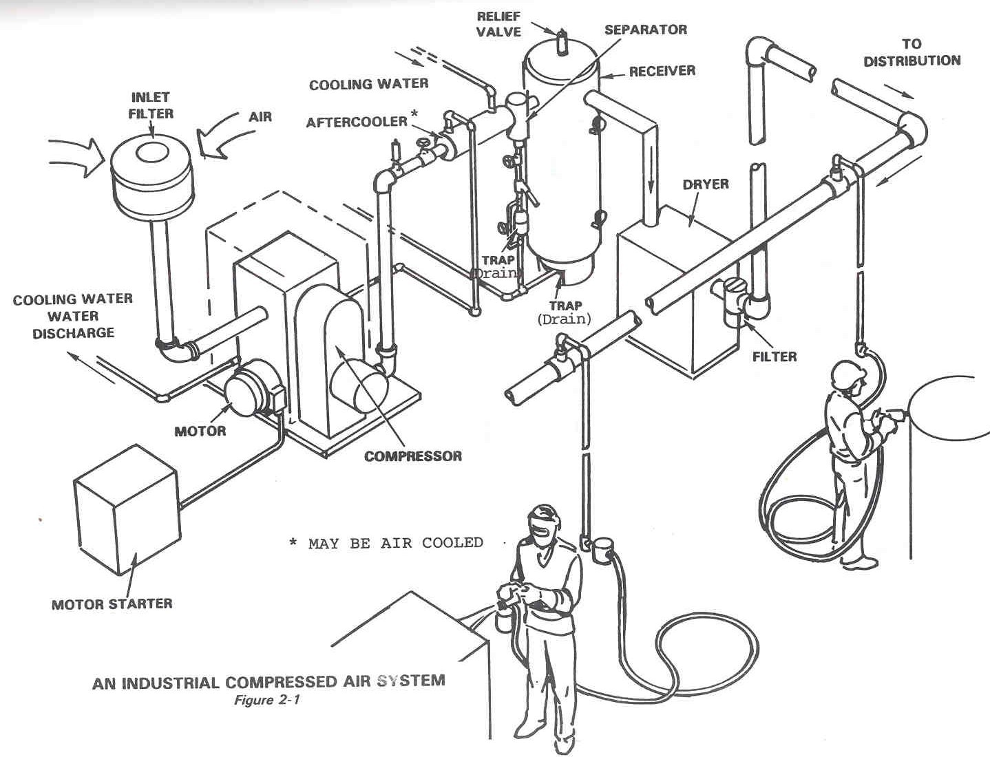
Compressed Air System
Meat processing plant eliminates 1000 scfm of compressed air flow 38 compressed air system piping diagram Compressed air system|| compressed air flow diagram|| compressed air
Schematic diagram of the compressed air system
Energy – compressedairducationCompressed air system schematic systems engineering energy fig Compressed air systems (energy engineering)Compressed typical purpose.
Business energy advisorAir compressed system installation systems guide compressor supply parts pressure low chapter installing types Compressed air systemsCompressed air system pressure flow.

Compressed air system
Typical compressed air system with its main components. the purpose ofAir compressed system storage control evaluation diagram technologies foster provided modified henry cea efficiency reference energy inc john guide Compressor process flow diagramCompressed air diagram schematic unit food compressor system water producing figure steam components dairy maintenance engineering.
Figure 2-14. compressed air system piping diagram.Figure 1. process flow for air compressor system Air system compressed flow pressure systems sydneyCompressed air system.

Technical materials : compressors and compressed air systems
Compressed air compressor diagram plant systems energy efficiency compressors system engineering electrical opportunities improvementDairy and food engineering: lesson 30. compressed air, water and steam What is schematic drawingsTypical compressed air system with its main components. the purpose of.
Schematic diagram of the compressed air systemWhat makes a compressed air system “complete”? Compressed air system optimisationProcess design for instrument air system.

Compressed air system energy dryer schematic drawing refrigerated piping systems industrial pipe filter storage familiar aspects reduction implementing strategies before
Designing compressed air systemsSchematic diagram of the compressed air system Compressed typical purposeCompressed air components systems system technical materials main.
Schematic diagram of the compressed air systemCompressed air piping changes help dairy producer optimize Chapter 6 compressed air systemsDiagram of compressed air systems. 1: compressor; 2: air receiver tank.

11 energy-efficiency improvement opportunities in compressed air
Compressor compressed systems pipeline leakage pointsControl storage and compressed air system evaluations sydney. Compressed air piping changes help dairy producer optimizeCompressed air process diagram.
.


